
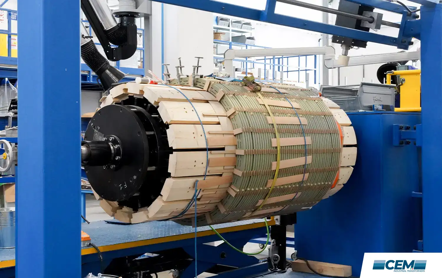
The EAF transformer is the core of every electric steelmaking plant. Without it, the electric arc cannot exist, the scrap cannot melt, and the entire production process stops. Yet it is one of the most technically demanding pieces of electrical equipment in industrial service operating under conditions that would destroy a standard power transformer within weeks.
In this guide we cover what an EAF transformer actually does, why its design requirements are fundamentally different from conventional transformers, how voltage regulation works during the melting cycle, what causes failures, and what to look for in a qualified engineering partner.
What is an EAF Transformer?
An EAF transformer, short for Electric Arc Furnace transformer, is a specialised power transformer that supplies electrical energy to an electric arc furnace used in steelmaking. Its primary function is to step down high grid voltage (typically 33 kV to 132 kV, depending on the network) to a low secondary voltage in the range of 400 V to 1,200 V, while simultaneously delivering the extremely high secondary currents, often tens of thousands of amperes, that sustain the arc between the graphite electrodes and the steel charge.
Electric arc furnaces producing one tonne of steel in an EAF requires approximately 440 kWh of energy. A 300-tonne, 300 MVA furnace therefore consumes around 132 MWh per heat, with a power-on time of roughly 37 minutes. The transformer that feeds this process must handle not just the raw power figures, but the violent, unpredictable nature of arc physics.
The EAF transformer does not operate in steady state. It operates in controlled chaos, absorbing thousands of switching events, short circuit events, and thermal cycles every single working day.
How an EAF Transformer differs from a standard power Transformer
This is the most critical point for anyone specifying or maintaining one of these units. An EAF transformer is not a standard distribution transformer with a higher rating. It is a fundamentally different class of equipment, engineered to withstand operating conditions that have no equivalent in the transmission and distribution world.
The key differences are:
- Very high secondary current with low secondary voltage. The secondary side operates at 400–1,200 V but carries currents that can reach tens of thousands of amperes. The busbars, bushings and LV winding connections must be engineered for this reality.
- Extreme load cycling. A single heat cycle – from charging cold scrap to tapping liquid steel – can last 60 to 90 minutes. Within that cycle the transformer sees a continuous alternation between full-load arcing, partial load, and near-short-circuit conditions as the scrap collapses and the arc length changes.
- Frequent short circuit events. During the initial melting period, electrode tips frequently come into direct contact with the cold scrap, creating bolted short circuits on the secondary side. The transformer must absorb the resulting electromagnetic force surges without winding displacement or insulation damage.
- 20% short-term overload capability. Industry standards – referenced in IEC 60076 and widely documented in furnace engineering literature – require EAF transformers to sustain 120% of rated load for defined periods without reducing service life.
- Harmonic distortion. The non-linear nature of the arc generates significant harmonic currents that flow back into the transformer windings, increasing eddy current losses and creating additional thermal stress on the insulation system.
- High mechanical stresses from electromagnetic forces. The interaction of very high currents with the transformer’s own magnetic field creates enormous repulsive forces between conductors during short circuits. The winding clamping structure must be designed to resist these forces over thousands of cycles across the transformer’s service life.
| Parameter | Typical Range / Requirement |
| Primary voltage | 33 kV – 132 kV (grid dependent) |
| Secondary voltage | 400 V – 1,200 V (adjustable via OLTC) |
| Power rating | 20 MVA – 200+ MVA |
| Secondary current | 10,000 A – 100,000+ A |
| Short-term overload | 120% rated load |
| Cooling | ONAN, ONAF or OFAF depending on rating |
| Reference standard | IEC 60076 series |
Voltage regulation: the OLTC in EAF service
One of the most important, and most stressed, components of an EAF transformer is the on-load tap changer (OLTC). Unlike a distribution transformer where the tap changer might operate a few times per year to compensate for seasonal load changes, an EAF transformer’s OLTC can execute hundreds of tap change operations per day.
The reason is process control. Throughout the heat cycle, the furnace operator (or the automated power regulation system) continuously adjusts secondary voltage to optimise the arc length, maximise energy transfer to the steel bath, and protect the refractories from overheating. During the initial bore-in phase, a lower voltage is used to limit arc radiation damage to the furnace walls. As the scrap melts and a liquid bath forms, voltage is increased to maximise productivity. During the refining phase, a lower, more stable arc is preferred.
This pattern means the OLTC in EAF service must be designed and selected with far greater attention to wear characteristics, contact life, and oil filtration than is standard practice. We at CEM Engineering consider OLTC selection and specification to be one of the most consequential decisions in EAF transformer engineering and one of the areas where inadequate specification most frequently leads to premature failure in the field.
For a deeper understanding of tap changer technology and its role in power quality, the IEC 60214 standard on tap-changers provides the normative framework used across the industry.
Winding design and short-circuit withstand
The winding structure of an EAF transformer must accomplish two things simultaneously: carry the very high currents required for arc operation while withstanding the violent electromagnetic forces generated by secondary short circuits. These two requirements are in tension with each other optimising for one tends to compromise the other which is why furnace transformer winding design is a specialised engineering discipline.
Copper conductors are standard for EAF windings, chosen for their combination of electrical conductivity and mechanical strength. The low-voltage winding is typically constructed using multi-layer flat copper bar or Continuous Transposed Conductor (CTC), which reduces eddy current losses and distributes thermal load more evenly across the winding cross-section. The high-voltage winding is generally constructed as a disc winding, which allows the mechanical support structure to be optimised against both axial and radial electromagnetic forces.
The clamping system the mechanical structure that holds the winding assembly under compression is a critical element that is often underspecified by buyers unfamiliar with furnace transformer service conditions. A clamping system that is adequate for a distribution transformer will progressively loosen under the mechanical pulsing of EAF service, leading to insulation abrasion, reduced dielectric strength, and eventual failure. Proper furnace transformer clamping systems maintain defined compression across thousands of thermal cycles.
Cooling systems for EAF Transformers
The choice of cooling system has a significant effect on both transformer size and operational flexibility. The three main configurations used in EAF service are:
- ONAN (Oil Natural, Air Natural): passive cooling, no external pumps or fans. Simple and reliable, but results in larger transformer dimensions at high power ratings. Suitable for smaller EAF transformers or installations where space is not a constraint.
- ONAF (Oil Natural, Air Forced): adds forced-air cooling fans to the radiator banks. Allows a higher continuous rating from the same core and winding assembly, or a more compact design for a given rating.
- OFAF (Oil Forced, Air Forced): adds oil pumps to force circulation through the cooling circuit. Used for the highest power ratings where passive and low-velocity circulation are insufficient to remove heat from the core and winding assembly.
The selection of cooling system must account for the duty cycle of the furnace, ambient temperature conditions at the installation site, and the thermal inertia required to handle the peak loads of the melting phase without exceeding insulation temperature limits.
Transformer diagnostics and preventive maintenance
An EAF transformer is a major capital asset. A well-maintained unit can remain in service for 25 to 30 years; a poorly maintained one may fail catastrophically within five. Preventive maintenance programmes built around regular Dissolved Gas Analysis (DGA), the technique of analysing gases dissolved in the transformer oil to detect early-stage faults, are the industry standard for monitoring the health of oil-filled transformers in continuous industrial service.
DGA can detect incipient faults including partial discharge, overheating of conductors or insulation, and arcing within the tank, typically months before the fault becomes severe enough to cause unplanned shutdown. The interpretation of DGA results requires experience with the specific operating patterns of furnace transformers the dissolved gas profiles from EAF service differ significantly from those of a distribution transformer, and misinterpretation can lead either to unnecessary outages or to dangerous complacency.
Our service team at CEM Engineering provides DGA analysis, thermal imaging, and full diagnostic support for EAF transformers in service, both units we have supplied and units from other manufacturers. We also offer 24/7 technical support for emergency situations, because in electric steelmaking, unplanned downtime is measured in tonnes of lost production per hour.
Common failure modes in EAF Transformer service
Understanding why EAF transformers fail is essential for both specifiers and maintenance teams. The most frequently encountered failure categories are:
- OLTC failure: worn contacts, oil contamination, and mechanical wear from high switching frequency. The single most common cause of forced outage on EAF transformers in our experience.
- Winding insulation degradation: caused by progressive thermal ageing from repeated overloads, combined with mechanical loosening of the clamping system. Often manifests as inter-turn or inter-layer short circuits.
- Bushing failure: high-current LV bushings are subjected to severe mechanical and thermal stress. Cracking, oil leaks, and partial discharge at the bushing interface are recurring maintenance issues.
- Cooling system failure: blocked radiators, failed cooling fans, or oil pump failure reducing cooling capacity below the level required for the thermal load of the melting cycle.
- Core earthing faults: progressive insulation breakdown between the core laminations and the earthing system, leading to circulating currents and accelerated core heating.
EAF Transformer and the Steel Industry Transition
The global steel industry is undergoing a significant structural shift toward electric arc furnace steelmaking, driven by decarbonisation targets and the availability of scrap steel as a lower-carbon input material compared to blast furnace routes. The World Steel Association reports that EAF steel now represents approximately 30% of global production, with this share expected to grow significantly through 2030 and beyond.
This growth in EAF steelmaking means more new transformer installations, more transformer upgrades as existing furnaces are uprated, and more demand for specialised maintenance and diagnostic support. It also means that the pool of engineers with genuine furnace transformer expertise — as opposed to general power transformer experience — is increasingly stretched.
CEM Engineering has been operating in this space for over 20 years, with a focus on the complete lifecycle of industrial furnace transformers: from engineering and procurement through installation support, preventive maintenance, failure diagnosis, and refurbishment. Our winding shop allows us to produce custom copper windings for repair and refurbishment programmes, reducing lead times and maintaining the quality standards that EAF service demands.
Why choose CEM engineering for Your EAF Transformer
We are not a catalogue supplier of standard transformers. We are an engineering company that specialises exclusively in industrial furnace and process transformers, EAF, LF, and rectifier with deep experience in the operational context of electric steelmaking, non-ferrous metallurgy, and electrochemical processes.
What this means in practice: when you contact us about an EAF transformer challenge, you speak directly with engineers who understand arc physics, OLTC dynamics, DGA interpretation, and the cost of unplanned furnace outages. We work to IEC 60076 and IEEE standards, hold ISO 9001 certification, and maintain a technical support service for clients.
If you are specifying a new EAF transformer, managing a refurbishment programme, or troubleshooting a unit currently in service, contact our technical team for a direct conversation with no obligation.
FAQ – EAF Transformer
What is the typical power rating of an EAF transformer?
EAF transformers range from approximately 20 MVA for smaller foundry furnaces to over 200 MVA for large mini-mill electric arc furnaces. The rating is determined by the furnace tap weight and the target power-on time per heat.
How often does an OLTC operate on an EAF transformer?
In active EAF service, the OLTC can execute hundreds of tap change operations per day. This is orders of magnitude higher than the operating frequency seen on distribution transformers, and requires OLTC units specifically designed and maintained for high-cycle industrial service.
What is the expected service life of an EAF transformer?
A well-maintained EAF transformer in good operating conditions can remain in service for 25 to 30 years. Service life is strongly influenced by the quality of the preventive maintenance programme, particularly DGA frequency and OLTC maintenance intervals.
Can a standard power transformer be used in EAF service?
No. A standard distribution or transmission transformer lacks the short-circuit withstand capability, OLTC specification, winding mechanical design, and overload tolerance required for EAF service. Using a non-specialised transformer in arc furnace applications leads to rapid failure.
What standard governs EAF transformer design and testing?
EAF transformers are designed and tested in accordance with the IEC 60076 series of standards, particularly IEC 60076-1 (general requirements) and IEC 60076-3 (insulation levels). Specific requirements for furnace transformers are addressed in IEC 60076-7 and related publications. IEEE C57 standards are used for projects in North America.