
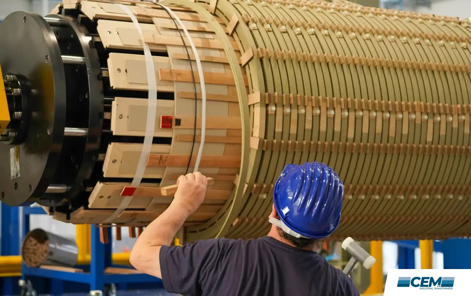
The ladle furnace transformer is the electrical heart of the secondary metallurgy stage in electric steelmaking. While the EAF transformer captures attention with its raw power figures, the LF transformer is equally critical to the final quality of the steel produced, because the ladle furnace is where chemical composition is refined, inclusions are removed, and temperature is precisely controlled before continuous casting.
Getting the LF transformer wrong, either in specification or in maintenance, means inconsistent steel quality, extended tap-to-tap times, and ultimately higher production costs. This guide explains how LF transformers work, how they differ from EAF transformers, and what to look for when specifying or maintaining them.
What is a Ladle Furnace Transformer?
A ladle furnace transformer is a specialised furnace transformer that provides power to a ladle furnace (LF), the secondary metallurgical unit where liquid steel, transferred from the primary melting furnace (EAF, converter, or induction furnace), is refined, homogenised, and brought to the precise temperature required for continuous casting. As noted by Britannica’s metallurgy reference, the ladle furnace uses an 8 to 25 MVA transformer with three graphite electrodes to provide arc heating, with the ladle itself acting as the furnace shell.
The LF transformer steps down grid voltage to a secondary voltage in the range of 150 V to 500 V, generating arc currents sufficient to maintain and precisely control the temperature of the liquid steel bath. Unlike the EAF, which must deliver maximum power during an intensive melting phase, the LF transformer operates in a more controlled, sustained arc heating mode, oriented around temperature maintenance and metallurgical reaction management rather than bulk energy input.
In the best-practice production line, Primary Furnace + Ladle Furnace + Continuous Caster, the LF is often described as ‘the soul of the process’. The quality of the LF transformer’s power delivery directly determines the quality of the steel that emerges from the caster.
LF Transformer vs EAF Transformer: The key differences
The distinction between LF and EAF transformer requirements is frequently misunderstood, sometimes with costly consequences. Both are furnace transformers, both operate under IEC 60076, and both require robust short-circuit withstand capability. But their operating profiles are fundamentally different.
| Characteristic | EAF Transformer vs LF Transformer |
| Primary function | EAF: bulk melting of scrap. LF: temperature control and chemical refining of liquid steel. |
| Power rating | EAF: typically 40–200+ MVA. LF: typically 8–40 MVA. |
| Secondary voltage | EAF: 400–1,200 V (wide regulation range). LF: 150–500 V (narrower range, finer control). |
| Arc stability | EAF: highly unstable during melt phase, frequent short circuits. LF: more stable arc, lower short circuit frequency. |
| Load cycle | EAF: violent cycling across a 60–90 minute heat. LF: sustained lower-intensity arcing over a defined treatment time. |
| OLTC duty | EAF: hundreds of operations per day. LF: fewer operations, but still elevated vs. distribution service. |
| Key design challenge | EAF: short circuit withstand and mechanical robustness. LF: precision voltage regulation and sustained thermal performance. |
Operating conditions of the Ladle Furnace Transformer process
Understanding the transformer requirements starts with understanding the ladle furnace process. After tapping liquid steel from the EAF or converter into the ladle, the ladle is transferred to the LF station, where three graphite electrodes are lowered through the lid and arcing begins. The objectives of the LF treatment are:
- Temperature adjustment: heating the steel bath to the precise target temperature for casting, typically within ±5°C of specification.
- Chemical composition control: adding alloying elements (e.g., manganese, silicon, aluminium, chromium) and adjusting carbon content to meet the grade specification.
- Inclusion removal: argon stirring, introduced through a porous plug in the ladle bottom, promotes flotation of non-metallic inclusions to the slag layer, improving steel cleanliness.
- Homogenisation: eliminating temperature and composition gradients within the liquid steel bath.
The LF transformer must support this process by delivering precise, stable arc power across the entire treatment time. The ability to adjust secondary voltage in fine increments, through a well-functioning OLTC, is critical to the process metallurgist’s ability to control arc length, heat input rate, and bath stirring intensity.
Voltage regulation in Ladle Furnace Transformer service
Precision voltage regulation is the defining technical requirement of the LF transformer. Unlike the EAF, where the OLTC is used to manage violent transitions between operating phases, the LF OLTC is used to fine-tune arc power input throughout a sustained treatment period.
This requires a transformer with a well-designed tap winding that delivers uniform voltage steps across the regulation range, an OLTC with low contact resistance variation between positions, and a regulation scheme that matches the precision requirements of modern LF process automation systems.
The secondary voltage range and the number of tap positions are defined in the transformer specification based on the furnace capacity, electrode diameter, and target arc power curve. For LF transformers serving large capacity ladles, precision on-load voltage regulation across the full range is specified for all production. Our team at CEM Engineering works closely with clients to define the correct tap structure based on the actual process requirements of their ladle furnace.
Short-circuit withstand in LF service
Although the LF process involves a more stable arc than the EAF melting phase, short circuit events still occur. Electrode tips can contact the bath surface or slag skull; electrical disturbances can interrupt the arc and cause re-strike events. The LF transformer must be designed to withstand these events without mechanical or electrical damage.
IEC 60076-5 defines the short-circuit withstand requirements for power transformers, and these requirements are applied, with the specific considerations of furnace service, to LF transformer specifications. The winding assembly must maintain its dimensional stability and clamping pressure under the peak electromagnetic forces generated by bolted secondary short circuits.
In our experience, one underappreciated aspect of LF transformer short-circuit performance is the cumulative effect of many moderate short-circuit events over years of service. Each event causes a small incremental loosening of the winding assembly; a transformer that passes a factory short-circuit test with excellent margins may have significantly reduced margins after five years of intensive LF service without a winding inspection.
We recommend winding condition inspection, including axial clamping force measurement and visual inspection of the winding assembly, as a standard component of the major overhaul programme for LF transformers at five-year intervals.
Thermal design and overload capability
LF transformers are typically specified with a continuous overload capability of 120% of rated load, consistent with the general requirement for furnace transformers under IEC 60076. This overload margin is necessary because production schedules do not always allow the luxury of operating exactly at rated load, particularly during periods of high demand or when a heat is running behind schedule.
The thermal design must ensure that the winding hotspot temperature remains within the limits that guarantee the expected insulation life, defined under IEC 60076-7 for oil-immersed transformers, even at sustained overload conditions. Cooling system sizing, winding copper cross-section, and the design of the oil circulation circuit must all be coordinated to achieve this.
Preventive maintenance for LF Transformers
A robust preventive maintenance programme is the most cost-effective investment in LF transformer reliability. The cornerstone of this programme is regular oil sampling for Dissolved Gas Analysis (DGA), conducted at intervals defined by the operational intensity of the unit, typically every three to six months for transformers in continuous industrial service.
DGA detects incipient faults that have no external symptoms: localised overheating of windings or core, partial discharge in the insulation, and low-energy arcing within the tank. Early detection of these fault conditions allows planned intervention before they escalate to forced outage.
Beyond DGA, the key maintenance activities for LF transformers include:
- OLTC inspection and maintenance: contact wear measurement, oil sampling from the OLTC compartment, and mechanism lubrication at intervals defined by the number of operations completed.
- Bushing inspection: visual inspection and infrared thermography to detect hotspots or early-stage oil leaks.
- Oil treatment or replacement: dielectric strength testing and moisture measurement of the transformer oil, with filtration or treatment as required to maintain oil quality within specification.
- Cooling system maintenance: fan motor inspection, radiator cleaning, oil pump performance check.
- Winding clamping check: verification of axial compression forces, particularly after any significant short-circuit event.
Integration of LF Transformer in the EAF + LF + CCM production route
The LF transformer does not operate in isolation. It is part of a coordinated production system, the Electric Arc Furnace + Ladle Furnace + Continuous Casting Machine route, that defines the economics and quality output of the modern mini-mill. Understanding the transformer’s role within this system is essential to specifying it correctly and operating it efficiently.
The LF treatment time is a bottleneck variable in production scheduling. A transformer that cannot deliver the required heating rate, due to inadequate rating, degraded OLTC performance, or cooling system limitations, extends LF treatment time and ripples backward into the EAF schedule, reducing overall plant productivity.
We at CEM Engineering have extensive experience with LF transformer installation in the context of complete steelmaking lines. Our EAF transformer and LF transformer capabilities allow us to take a coordinated view of the electrical requirements across the entire furnace line, not just the individual unit.
Why choose CEM engineering for your LF Transformer
Our focus is exclusively on industrial furnace and process transformers. We do not offer general-purpose distribution transformers, our entire engineering capability is oriented around the specific technical requirements of metallurgical and electrochemical processes. This means that when you discuss an LF transformer project with us, you are talking to engineers who understand the process, not just the electrical equipment.
We offer engineering consultation from the specification phase, including tap structure definition and OLTC selection; supply chain management for new transformers built to your specification; and a full service capability including DGA analysis, winding inspection, OLTC refurbishment, and 24/7 emergency support.
Contact our team at CEM Engineering to discuss your ladle furnace transformer requirements.
FAQ – Ladle Furnace Transformer
What is the typical MVA rating of an LF transformer?
LF transformers typically range from 8 MVA for smaller ladle capacities to 40 MVA for large-capacity ladles serving high-productivity steel plants. The rating depends on ladle size, target heating rate, and treatment time requirements.
What is the main difference between an EAF transformer and an LF transformer?
The EAF transformer is designed for maximum power delivery during an intensive melting cycle with violent load cycling and frequent short circuits. The LF transformer is designed for precise, sustained arc heating during the refining phase — lower power, finer voltage regulation, and more stable arc conditions.
How often should an LF transformer be serviced?
DGA oil sampling should be performed every three to six months. OLTC inspection intervals should be defined by the number of operations, typically every 50,000 to 100,000 operations or annually, whichever is sooner. Full winding inspection is recommended every five years.
Can an EAF transformer be used as an LF transformer?
Technically possible in some cases, but generally not recommended. EAF transformers are typically oversized for LF service and lack the fine-resolution tap structure required for precision temperature control in secondary metallurgy. A properly specified LF transformer will outperform an adapted EAF unit in the LF application.
What is dissolved gas analysis and why is it important for LF transformers?
Dissolved Gas Analysis (DGA) is a diagnostic technique that analyses gases dissolved in transformer oil to identify incipient faults such as overheating or partial discharge. It is the most cost-effective early warning system available for oil-immersed transformers and is essential for preventing unplanned outages. See our service activities page for more information on DGA and our full diagnostic offering.