
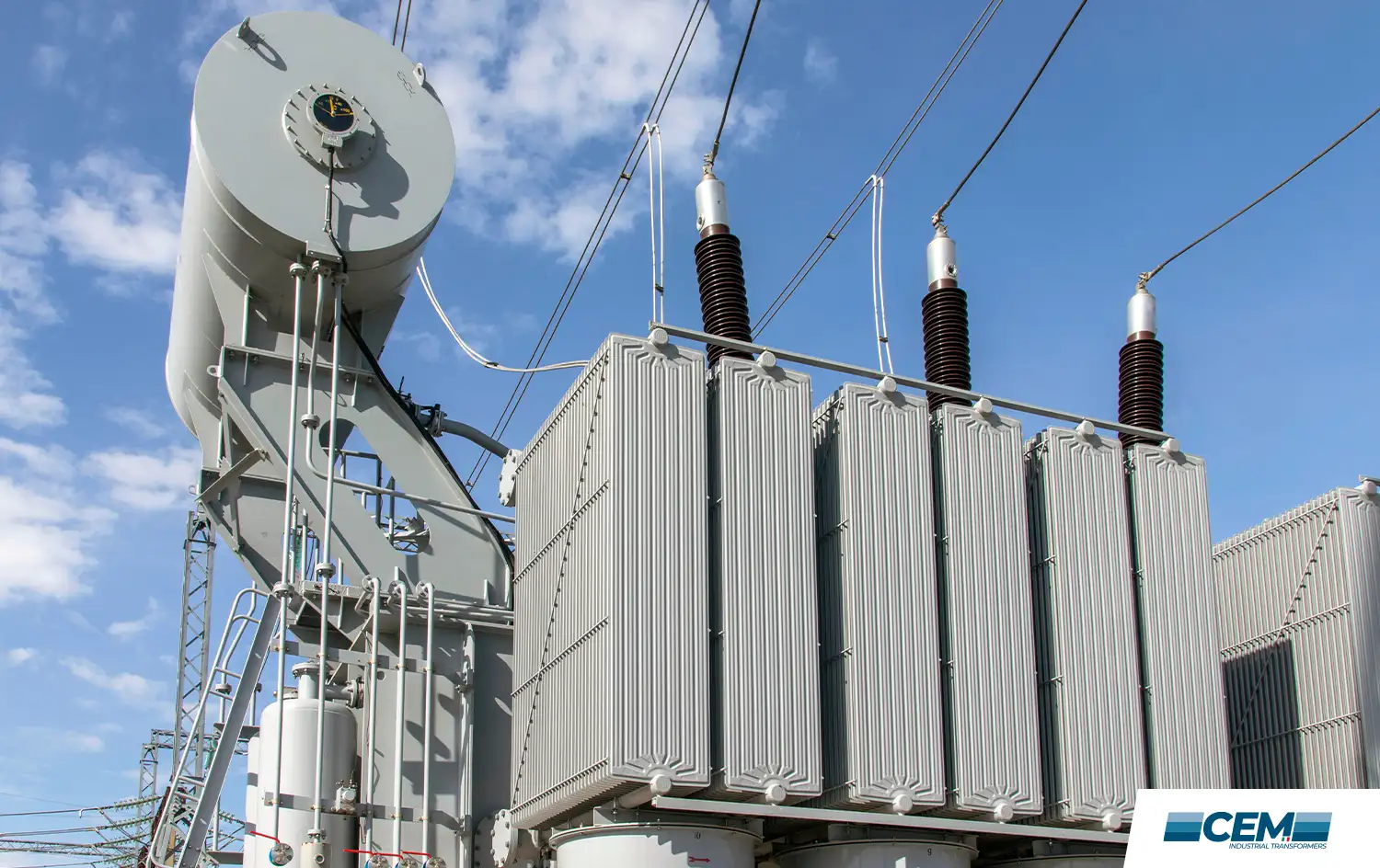
The rectifier transformer is one of the least visible but most critical pieces of electrical infrastructure in heavy industry. Every aluminium smelter, every chlor-alkali plant, every electroplating line, every DC motor drive system, and every railway traction substation depends on a rectifier transformer to convert AC power from the grid into the controlled DC that the process requires.
Unlike standard power transformers, rectifier transformers must handle non-linear currents, high harmonic content, continuous full-load operation, and, in many applications, very high DC output currents. Getting the specification right has significant consequences for grid power quality, process efficiency, and long-term equipment reliability.
What is a rectifier transformer?
A rectifier transformer is a specialised transformer designed to interface between an AC power supply and a rectifier system, a set of diodes or thyristors that converts alternating current to direct current. The transformer performs two distinct functions: it steps down or adjusts the AC voltage to the level required by the rectifier and the downstream DC process, and it provides the electrical isolation between the AC grid and the DC system.
As described in industry technical literature, rectifier transformers are essential across a wide spectrum of industrial applications: from giant aluminium electrolysis production lines to urban subway traction power grids, from rolling mill drive systems to industrial electrochemical reactors. In each case, the quality and stability of the DC output is directly dependent on the design of the rectifier transformer feeding the system. Hitachi Energy’s technical documentation on rectifier transformers provides a useful overview of the application landscape.
A rectifier transformer is not a standard transformer used with a rectifier. It is a specially engineered unit whose winding design, insulation system, and cooling are all optimised for the non-sinusoidal currents and continuous full-load operation that rectifier service demands.
Why rectifier transformers are different from standard power transformers
The fundamental challenge of rectifier transformer design is that the secondary current is not sinusoidal. The rectifier’s switching action, diodes conducting alternately, creates current waveforms that contain significant harmonic content. These harmonics cause additional losses in the transformer (eddy current losses in the windings, stray losses in structural parts), create heat distribution anomalies, and can interfere with the upstream grid if not managed through proper transformer design.
The key design considerations that distinguish rectifier transformers from standard units are:
- Current waveform distortion: the secondary current contains large odd harmonics (5th, 7th, 11th, 13th in a 6-pulse system). The winding insulation and cooling system must be designed to handle the additional losses these harmonics create.
- Continuous full-load operation: unlike furnace transformers that operate on a cyclic duty, many rectifier transformer applications require continuous rated operation 24 hours a day. There is no cooling recovery period, the transformer must be sized for permanent steady-state thermal equilibrium at full load.
- Very high DC output currents: applications such as aluminium electrolysis require DC currents of tens of thousands of amperes. The LV winding and busbar connections must be engineered for this level of continuous current-carrying.
- Insulation coordination: the secondary windings in rectifier service are subject to voltage stress patterns that differ from those in AC transformer service, requiring specific attention to insulation design and testing.
Phase-shifting and multi-pulse rectification
The most important tool available to the engineer specifying a rectifier transformer for minimising harmonic injection into the upstream AC network is the phase-shifting multi-pulse configuration. This is the technical heart of modern industrial rectifier transformer design, and understanding it is essential for anyone involved in specifying, procuring, or maintaining these units.
In a basic 6-pulse rectifier system, a three-phase transformer secondary feeds a three-phase bridge rectifier. The resulting DC output has a ripple frequency of six times the AC supply frequency, and the AC input current contains significant 5th and 7th harmonic components that inject harmonic distortion into the grid.
By providing a transformer with two or more secondary windings, each displaced by a defined phase angle relative to the others, and feeding each secondary into its own rectifier bridge, the harmonic components of the individual bridges cancel each other partially or completely in the primary current. The result is a higher-pulse rectification system with substantially lower harmonic content:
- 12-pulse system: two secondary windings, one star-connected and one delta-connected, each feeding a 6-pulse bridge. The 5th and 7th harmonics cancel on the primary side; the lowest remaining harmonics are the 11th and 13th. Widely used in industrial applications where harmonic limits under IEEE 519 or IEC 61000 standards must be met.
- 24-pulse system: four secondary windings with appropriate phase shifts. 5th, 7th, 11th, and 13th harmonics cancel; lowest remaining harmonics are 23rd and 25th. Used where stricter harmonic limits apply.
- 60-pulse system: used in large aluminium smelter potlines where five 12-pulse rectifier groups are connected in parallel with graduated phase-shift angles (−12°, −6°, 0°, +6°, +12°). This configuration delivers harmonic performance approaching that of a pure DC source.
The design of the phase-shifted secondary windings, the precise inter-winding angles, the turns ratio, the impedance balance between secondaries, requires specialised transformer engineering. Our rectifier transformer engineering capability at CEM covers the full range of multi-pulse configurations, from standard 12-pulse units to custom multi-secondary arrangements for demanding electrolysis applications.
Industrial applications of rectifier transformers
Rectifier transformers serve a diverse range of industrial applications, each with its own specific requirements for DC voltage, current, pulse number, and regulation. The main application sectors are:
Aluminium smelting – electrolysis (hall-héroult process)
Aluminium production by the Hall-Héroult electrolytic process is the largest single consumer of rectifier transformer capacity worldwide. Each electrolysis cell (pot) operates at a DC voltage of approximately 4–5 V, and smelter potlines typically consist of hundreds of pots connected in series, requiring DC supply voltages in the range of 700–1,000 V at currents of 150,000 A to 500,000 A.
At these scale levels, the transformer-rectifier system (known in the industry as a ‚rectiformer‘) is typically configured as a 60-pulse system to achieve the harmonic performance required by national grid codes. The continuous nature of the electrolysis process means these transformers operate at or near full load continuously — often for years between planned maintenance outages.
Chlor-alkali and electrochemical production
The production of chlorine and sodium hydroxide by electrolysis of brine, and the production of other electrochemical products (hydrogen, fluorine, sodium metal), all depend on rectifier transformers providing stable, ripple-free DC power to the electrolysis cells. The requirement for very stable DC voltage, since voltage fluctuations directly affect product quality and current efficiency, places high demands on the transformer’s regulation characteristics and the smoothness of the rectified output.
Mining and minerals processing
Electrowinning and electrorefining processes for copper, zinc, nickel, and other metals use large rectifier transformer installations to drive the electrodeposition reactions. As with aluminium, these are continuous processes running at high DC currents, with transformer reliability being critical to plant throughput.
Railway traction substations
DC traction networks, used by metropolitan railways, tramways, and some mainline rail systems require rectifier substations that convert 50 Hz AC supply to 750 V DC (for tramways), 1,500 V DC, or 3,000 V DC for traction supply. The rectifier transformers in these substations must handle the highly variable, rapidly fluctuating load presented by accelerating and braking trains, while maintaining the supply voltage within the limits defined by standards such as EN 50163 for railway traction power supply.
Industrial DC motor drives
Large DC motors, used in rolling mills, mine hoists, paper machines, and other high-torque variable-speed applications, are fed from rectifier systems that require dedicated rectifier transformers. The CEM Engineering service team has extensive experience with transformer and rectifier maintenance in these applications, where motor drive availability directly determines plant production output.
Harmonic mitigation and power quality
Grid harmonic distortion is a regulated parameter in most industrial electricity supply contracts. Standards including IEEE 519 (used in North America) and IEC 61000-3-12 (used in Europe and internationally) define maximum allowable harmonic current injection at the point of common coupling. Exceeding these limits can result in financial penalties, supply authority intervention, or interference with other equipment on the same network.
For large rectifier installations, achieving compliance with harmonic limits through transformer phase-shifting design alone is the most cost-effective approach, compared with the alternative of installing passive harmonic filters or active power quality correction equipment after the fact. This is why harmonic analysis should be conducted early in the design process for any significant rectifier installation, and the transformer specification should include explicit harmonic performance requirements.
Total Harmonic Distortion (THD) targets for compliant installations typically require THD below 5% at the point of common coupling. A correctly specified 12-pulse rectifier transformer system can typically achieve THD in the range of 8–12% without additional filtering; a 24-pulse system can achieve THD below 5%; and higher-pulse configurations achieve even lower levels.
Specification considerations for industrial rectifier transformers
When specifying a rectifier transformer, the following parameters must be defined precisely to ensure the delivered unit meets both the process requirements and the applicable power quality standards:
- DC output voltage and current: the nominal operating point and any regulation range required by the process.
- Pulse number: determined by the harmonic analysis of the installation and the applicable grid code.
- Phase shift angles: for multi-secondary configurations, the precise inter-winding phase displacement.
- Impedance: the transformer impedance (short-circuit voltage) affects both the commutation reactance of the rectifier and the short-circuit current contribution to the DC bus.
- Cooling system: ONAN, ONAF, or OFAF, depending on the continuous rating and ambient conditions.
- Voltage regulation: whether an on-load tap changer is required, and the regulation range needed for process control.
- Standards: IEC 60076 (international) or IEEE C57 (North America), plus any application-specific standards for the sector.
- Testing requirements: factory acceptance test (FAT) requirements, including heat-run test, short-circuit impedance measurement, and harmonic distortion verification.
Maintenance of rectifier transformers
Rectifier transformers in continuous industrial service are among the highest-duty transformer applications. The combination of non-sinusoidal currents, elevated winding temperatures from harmonic losses, and continuous operation creates an insulation ageing regime that is more demanding than equivalent kVA-hours in standard power transformer service.
Our recommended maintenance approach for rectifier transformers includes regular Dissolved Gas Analysis every three months for transformers in continuous high-load service, combined with oil quality testing (dielectric strength, moisture content, acidity), bushing infrared thermography, and winding resistance measurement at the annual maintenance outage.
Thermal imaging during operation, using an infrared camera to identify hotspots on the transformer tank, radiators, and bushing connections, is a particularly valuable technique for rectifier transformers, where the non-uniform current distribution caused by harmonic loading can create localised overheating that is not reflected in the average winding temperature.
Why choose CEM engineering for rectifier transformers
Rectifier transformer engineering is a specialised discipline that combines power transformer design expertise with detailed understanding of power electronics, harmonic analysis, and the process requirements of electrolytic and DC motor drive applications. General-purpose transformer suppliers rarely have the depth of experience in this field that process-critical industrial applications demand.
We at CEM Engineering work exclusively in the industrial transformer space, with a focus on the most technically demanding applications: EAF and LF furnace transformers and industrial rectifier transformers for metallurgical, chemical, and traction applications. Our engineering team understands the processes that our transformers serve, which means we can engage with our clients as technical partners, not just as equipment suppliers.
We operate from our facility in Cologno al Serio (Bergamo, Italy) with a North American presence in Coraopolis, PA, and we provide 24/7/365 technical support to clients in Europe and North America. Our winding shop allows us to produce custom copper windings for new transformers and refurbishment projects, maintaining quality and reducing lead times for time-critical programmes.
To discuss a rectifier transformer project or service requirement, contact our technical team.
FAQ – rectifier transformer
What is the difference between a 6-pulse and a 12-pulse rectifier transformer?
A 6-pulse system uses a single secondary winding feeding one three-phase bridge rectifier. A 12-pulse system uses two secondary windings, one star and one delta connected, feeding two bridge rectifiers. The 12-pulse configuration cancels the 5th and 7th harmonic components, significantly reducing harmonic injection into the supply network and improving DC output quality.
Why is Total Harmonic Distortion (THD) important for rectifier transformer installations?
THD is a measure of the distortion of the AC current waveform caused by harmonic components. High THD can cause overheating of supply equipment, interference with other loads on the network, and non-compliance with grid codes such as IEEE 519. Proper rectifier transformer design through phase-shifting is the most cost-effective way to control THD at source.
What cooling systems are used on industrial rectifier transformers?
Most industrial rectifier transformers use ONAN (Oil Natural, Air Natural) or ONAF (Oil Natural, Air Forced) cooling. For very high-power continuous-duty applications such as aluminium smelter rectiformers, OFAF (Oil Forced, Air Forced) cooling is common to handle the continuous full-load thermal dissipation requirement.
Can a rectifier transformer be used without a tap changer?
In applications where the DC voltage is fixed and process conditions do not require adjustment, a transformer without an OLTC (no-load tap changer only) is an option. However, many industrial processes benefit from voltage regulation capability, particularly during start-up, under varying load conditions, or when the process requires adjustment to maintain quality.
What standards apply to industrial rectifier transformer design?
Industrial rectifier transformers are designed and tested in accordance with IEC 60076 (general transformer requirements) and IEC 61378 (series specifically addressing converter transformers). IEEE C57.18.10 is the relevant North American standard. Application-specific standards apply in sectors such as railway traction (EN 50329).